
Back to Aerodynamic Design of Aircraft with Computational Software
Back to overview: Preamble Exercises and Projects
Chapter 9[pdf]:
9.1 Introduction to Aerodynamic Wing Design
9.2 Subsonic Straight-Wing Design
9.3 Transonic Swept-Wing Design
9.4 Supersonic Slender-Wing Design
9.5 Further Configuration Development
9.6 Wing-Body Mathematical Shape Optimization
Tutorials: ceasiompy Euler workflow
Exercises and Projects – software SU2 and Tornado
Introduction
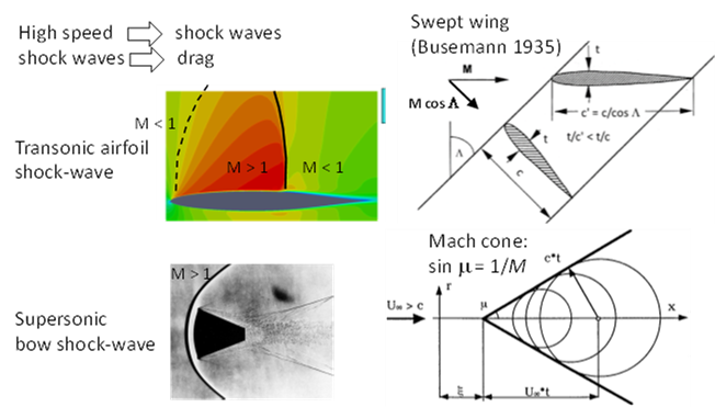
This chapter studies 3D flow close to and over M 1, see Fig. 1
The computer labs for Ch 7 and Ch 8 studied the transonic flow over a wing profile and we found how hard it is to make the drag rise small by shaping the airfoil with given max thickness.
But a swept wing can decrease drag. An infinite swept wing (constant chord) in inviscid flow at Mach-number M has no pressure gradient parallel to the leading edge so pressure forces are the same as for the unswept wing at
M cos Λ (1)
This is not quite true for a finite wing, but the sweep does decrease the shock strength since it will be at an angle to the free stream. Wave drag is essentially an inviscid phenomenon and can be modeled well by the Euler equations. But we see that a shockwave interacts with the boundary layer on the wing by the jump in pressure across it, upper left, and this may be important.
Figure 1 shows also the Mach cone for supersonic flow, how the pressure disturbances created by the wing travel out at the speed of sound (here c) while the wing travels forward at Mc > c. Then the wing is felt only inside the Mach cone, with apex at the wing nose and opening angle μ,
sin μ = 1/M (2)
Questions to consider before doing calculations
- Are (1) and (2) consistent? What sweep angle is necessary to make the wing leading edge exactly sonic at M 2?
- The fuselage protrudes in front of the wing and will be the apex of a Mach-cone. Find a picture of the M 2 Concorde with its S-curved wing leading edge.
Is the wing inside the M 2 Mach cone from the nose? Measure roughly the wing sweep on the inner part of the wing, the least swept mid-part, and the outer part. Are they all subsonic at M 2?
Wave drag
- The ModelIA geometry is in ModelIA.xml and ModelIA.smx. There is also a ModelR0 with quarterchord sweep 0 and no body. We wish to compare CFD inviscid predictions with the experiments by Betz & al in the book Fig. 9.xx on a straight wing and a rotated wing. To this end, create from ModelR0 a model ModelR45 with wing sweep 45o by rotating it in sumo (or cpacscreator). Run the Euler workflow with sumo automeshing and SU2 to compute the α = 0 drag in a Mach-sweep M = [0.5,0.7,0.8,0.9,1] for ModelR0 and ModelR45. Check if M cos L straight wing drag is equivalent to M swept wing Λ drag. What wing geometry would you change to make the agreement better?
- Run ModelIA α = 0 M = 0.9 with and without body. What dominates, wing or body drag? Then compute ModelIA with a few small angles of attack to check the formula (Eq. 3.17).
More about wave drag
Wave drag is exerted on the wing by the pressure forces influenced by a shockwave. The pressure loss comes from the thermodynamic process in the shock which converts kinetic energy into heat: entropy rises. When the flow is supersonic, also the disturbances to the flow from the presence of the aircraft are felt much further away. That opens the way to estimating drag forces from those disturbances at “infinity”, since they travel by the wave equation and allow analytic estimates.
Using this approach, it is found that a “Sears-Haack” shaped axisymmetric body has minimal wave drag for given length and volume,
r/rmax = [1 – (1 – 2x/L)2]p 0 < x < L
for p = 3/4, figure below for rmax /L = 1/18
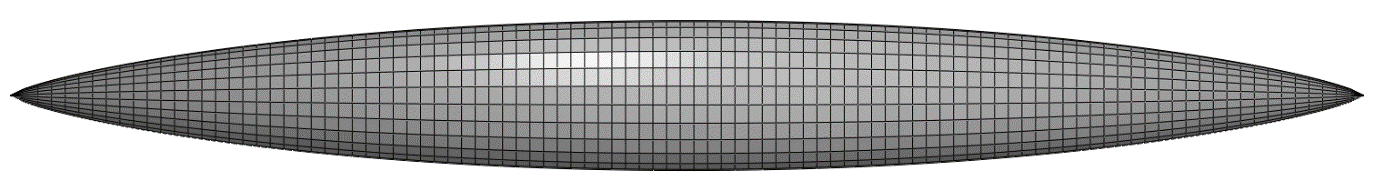
We wish to check this by computation with real inviscid compressible flow, and to this end, there are cpacs models called searshaackp05.xml ... searshaackp10.xml prepared which have the same length but different p and rmax to make their volumes the same.
- Find the relation between p and rmax to make the body volume equal that for rmax = 1/18 L and p = 3/4.
- How sharp is the nose? It looks sharp in Fig. 1, yet, it has a tangent plane at the nose, but its radius of curvature vanishes. For what 0 < p < infty is the nose
a cusp: dr/dx(x=0) = 0
sharp: dr/dx(x=0) > 0 and finite
flat: vanishing radius of curvature
blunt: radius of curvature > 0 finite
- Compute the drag at M 1.1 for the searshaackpxx models (SU2 workflow, Euler, alpha = beta = 0). For which p is there a visible subsonic region at the nose? For a sharp nose we expect an attached bow wave. Check the shock angle with the Mach cone angle.
Area rule
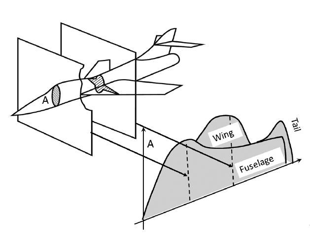
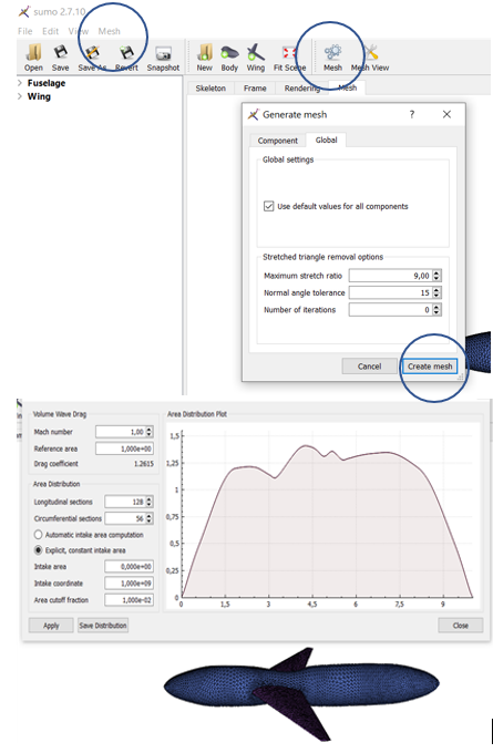
The “aera rule” says that the M 1 wave drag can be estimated from an axi-symmetric body with the same cross-section area distribution from nose to tail as the aircraft, Fig. 3
SUMO will compute this, and save a table, here for the simple wing-body on the right.
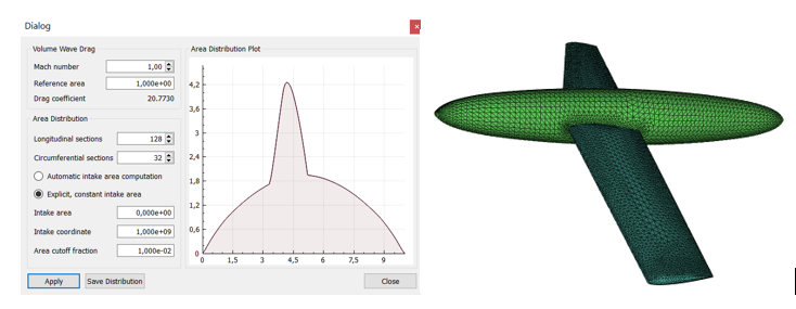
Create a mesh by clicking on the mesh icon. This brings up a sub-menu with mesh parameters and the standard (default) will work, so click on create mesh, view it in graphics window mesh. Mesh, top menu row, has a sub-menu wave drag estimation:
- Work interactively with sumo to area-rule the body of ModelIa. Do this by repeatedly manipulating the cross sections shown in the sumo Skeleton view, meshing, and plotting cross section area distribution for M 1 until the area distribution looks smooth, say for ModelIS. No modification should be done in front of the wing root, and none aft of the wing tip. Compare the drag with ModelIA and the given ModelIB the body of which is “perfectly” area ruled.
- Supersonic wing design for M 2. Choose a sweep L = 45o for an un-tapered quadrilateral wing of aspect ratio 6. Run a Mach-sweep from 1 to 2 at zero lift and record the wave drag. For what M is the wing swept inside the Mach-cone? Plot iso-mach contours in the (x,y)-plane and discuss the position of the “bow” shock.